The liquid crystal display is composed of a liquid crystal cell and a backlight assembly, and the backlight provides illumination of the liquid crystal panel with sufficient brightness and high uniformity to ensure the display quality of the liquid crystal display. In large-size liquid crystal products, CCFL (Cold Cathode Fluorescent Lamp) backlights with relatively mature and high surface brightness are often used [1][2]. In recent years, CCFLs have high power consumption, short life span and narrow color gamut ( Disadvantages such as only about 75% of NTSC are gradually being abandoned. LED (Light Emitting Diode) backlights have developed rapidly and occupied the market due to their advantages of energy saving, wide color gamut, strong color performance and long life. As LED light efficiency continues to increase and cost price decreases, LED backlights It will replace the CCFL backlight and become the mainstream backlight in the market [3][4]. Based on the analysis of the development prospects of LED backlights, this paper proposes a new type of edge-lit LED backlight, which can replace CCFL backlights in large-size LCD products, reducing cost and improving display quality.
1 Analysis of existing LED backlight types
The main function of the LED backlight is to convert the light from the LED point source into a uniform surface source. According to the different distribution positions of the light source in the backlight system, it is divided into two types: side light type and direct type [5].
1.1 Direct-lit LED backlight
The structure of the direct-lit LED backlight is shown in Figure 1. It mainly includes an array of LED light sources (arranged as shown in Figure 2), a reflective layer, a diffusing plate, a prism film, and the like. The design idea of ​​the LED backlight is to place the LED light source array and the PCB board on the bottom of the backlight module. The light emitted by the LED light source is reflected by the bottom surface and the side surface, and then uniformly emitted through the surface scattering plate and the brightness enhancement film. Direct-type LED backlights require multiple LED light sources, so their power consumption is high and heat dissipation problems are serious. Generally, special heat sinks are required. Therefore, most large-size LCD product manufacturers give up the use of such backlights and turn to research and development. Sidelight LED backlight.

1.2 edge-lit LED backlight
The structure of the edge-lit LED backlight is shown in Figure 3. It mainly includes the light source, the light guide plate, the light source reflector, and the prism to propagate forward in the presence of total reflection [7]. In order to obtain the side illumination, it needs to be on one side of the light pipe. The microstructure is added to destroy the total reflection condition. In this paper, one side of the light guide tube is added to the dot structure to scatter light, and a side light-emitting fine light guide tube is obtained. The working principle of the novel backlight is that the light emitted by the LED light source is coupled into the side light-emitting fine light guide tube, and is emitted from the side after multiple times of refraction, and is converted into a line light source with the same way as the CCFL, and then incident on the light guide plate. In the light guide plate, the conversion from the line source to the surface light source is completed, and then the light is uniformly and parallelly cast to the downward polarizer, and then the liquid crystal molecules and the upper polarizer are passed through to finally form an image.

2.2 Micro-light pipe light exit surface dot arrangement:
The backlight system requires high uniformity of light output, so it is necessary to design a light guide tube with uniform light. In the present scheme, the light guide surface of the micro light guide tube has a circular dot structure, and when the light is incident on the scattering mesh point structure, scattering occurs, the propagation direction is changed, and the light exiting surface is emitted. Since the propagation path is complicated after light scattering, in order to simplify the model, we consider the light uniformity of the light guide tube when the radius of the dot is constant.
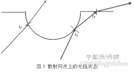
The LED light source can emit light at various angles, so after the light is coupled into the light pipe, the light in all directions is equal, and its propagation state is as shown in Fig. 5. According to the principle of total reflection, only those rays whose incident angle is smaller than the critical angle of total reflection can be emitted from the scattering point, and this part of the light can be calculated by taking the proportion of all the light reaching the dot.
