Abstract: A microphone array sound source localization system based on TMS320C6713 is presented. DSP is used as the core controller of the system. The McASP interface of TMS320C6713 is connected with A/D chip PCM4204, which overcomes the shortcomings of limited computing power and slow data processing of single-chip system, and can better meet the requirements of sound source localization of microphone array. The hardware design scheme and software design idea of ​​the system are introduced. The practice proves that the system has the advantages of real-time high speed, high precision and good reliability.
Keywords: microphone array; sound source localization; multi-channel audio serial port; register configuration
0 Introduction The sound source localization of the microphone array refers to picking up the sound signal by the microphone, and analyzing and processing the output signals of the microphone array to obtain the position information of one or more sound sources. If the sound source can continuously output sound, the positioning and tracking of the moving sound source can be realized by real-time analysis and processing of the signals received by the microphone array. At present, sound source positioning based on microphone arrays is widely used in voice communication environments with noisy backgrounds, such as venues, multimedia classrooms, and car phones to improve communication quality. This paper mainly discusses the hardware system design of sound source localization of microphone array, and makes some considerations for the software system design of sound source localization. The system is mainly used for the car flute sound positioning system, collects the flute signal through the microphone array, and realizes the positioning of the car according to the positioning algorithm.
1 hardware system design The hardware system mainly includes an array of multiple microphones, signal conditioning unit, data acquisition unit, algorithm processing unit, logic control unit, as shown in Figure 1. 
1.1 Microphone Array The microphone array in this design was implemented using Prestige's MPA416 microphone. The MPA416 microphone has a high sensitivity of 50 mV/Pa; it has low cost and low noise; the frequency response range is 20 Hz to 20 kHz; when it is used in an array, the phase difference of the MPA416 can be controlled from 3° to 5°. Within the system, it can meet the requirements of the system for accuracy and stability. Since the structure of the uniform line array is the simplest and the processing is convenient, the system adopts a one-dimensional linear microphone array with an array spacing of 10 cm.
1.2 Signal Conditioning Unit Since the sound signal picked up by the microphone is too small and susceptible to environmental noise, it is necessary to pre-process the sound signal and handle the signal conditioning unit to meet the requirements of the system. The system adopts a two-stage amplifying circuit, and the preamplifier is a low-noise amplifier. The main purpose is to change the microphone signal from single-ended to differential. Therefore, TI's low-noise amplifier OPA1632 is used, and the secondary amplifying circuit is a linear amplifying circuit.
1.3 Data Processing Unit In this design, the data processing unit selects TI's cost-effective floating-point DSP chip TMS320C6713 (hereinafter referred to as C6713) as the core of system algorithm processing. It has an improved Harvard architecture internally; it has 256 KB of on-chip memory; a rich set of peripherals including 2 multi-channel buffered serial ports (McBSP), 2 multi-channel audio serial ports (McASP), SPI and I2C, etc. Memory Access (EDMA) controller that controls 16 independent channels for data transfer without CPU intervention; 32 b external memory interface (EMIF) for seamless connection to SRAM, ERPOM, FLASH, SBSRAM and SDRAM. Therefore, the C6713 can satisfy the system's fast processing of some complex positioning algorithms.
1.4 Data Acquisition Unit The microphone array picks up the sound signal and processes it through the front-end conditioning unit so that the sound signal can meet the requirements of the A/D chip, thereby performing analog-to-digital conversion and sampling of the data.
The A/D converter in this design uses TI's PCM4204, a 24-bit, high-precision, 4-channel audio analog-to-digital converter with a sampling rate of 216 kHz. The chip has an audio serial port and a DSD data port, wherein the audio serial port can be conveniently connected with the DSP, and the sampled data can be quickly read by the DSP.
There are two ways to exchange data between McASP and ADC peripherals of TMS320C6713: use CPU to communicate with peripherals through serial port. This mode has slow transmission speed, small data exchange, and takes up CPU clock cycle. In order to achieve high-speed data acquisition, the system uses another method to utilize EDMA. This method can make full use of the hardware structure features of the TMS320C6713. The independent data and independent address bus of the ED-MA channel not only make the data transmission speed fast, the transmission volume is large, and it does not occupy the CPU clock cycle, but also enables data transmission and DSP command execution. Synchronously, the speed of the entire system is greatly improved.
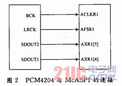
1.4.1 Connection with DSP chip The connection with PCM4204: is realized by the multi-channel audio serial port McASP1 of TMS320C6713. The connection diagram is shown in Figure 2. 
In Figure 2, the LRCK of PCM4204 is connected to AFSR1 of C6713. As a frame sync signal, BCK is a bit clock signal connected to ACLKR1; two data output pins SDO-UT1 and SDOUT2 of PCM4204 are respectively connected to AXR[4] and AXR[5] of McASP1 in DSP, when I2S data format is used. When SDOUT1 outputs 1, 2 channels of data, SDOUT2 outputs 3 or 4 channels of data. The PCM4204 generates LRCK and BCK signals to drive the AFSR1 and ACLKR1 of the DSP.
1.4.2 Setting the Sampling Chip Operating Mode In order for the system to work properly, the PCM4204 needs to be set. Configuration is possible through the chip pins S/M, FMT2, FMT1, FMT0, FS2, FS1 and FSO. details as follows:
(1) s / M = 0, so that PCM4204 works in the main mode;
(2) FMT2=O, FMT1=0, FMTO=1, select I2S with audio data format of 24 b, and its format is shown in Figure 3; 
(3) FS2=1, FS1=0, FS0=1, and the sampling rate is 96 kHz;
2 interface program preparation
2.1 Initialization In order for the DSP's McASP1 port to receive data, you need to write the appropriate program. Since EDMA is used for data transmission, it is necessary to initialize McASP and EDMA first, that is, set the relevant registers of McASP1 according to the design requirements of the hardware interface of the circuit system, so that it works in EDMA mode.
(1) EDMA receiving configuration. Set the opt, src, cnt, dst, idx, and rld registers of EDMA separately, and set the data length to 32 b through the opt register. The source data and destination data are in one-dimensional mode, the source address is fixed, and the destination address is indexed. Enable frame synchronization, etc., and write the source and destination addresses to the src, dst registers, respectively. The cnt register is mainly used to configure the frame count and unit count. Since the data format of I2S is adopted, one frame of data contains only two unit data. By configuring the idex and rld registers, the destination data can be stored in the set index.
(2) Configuration of McASPl. Set registers such as PFUNC, PDIR, SRCTL, RFMT, AFSRCTL, ACLKRCTL and AHCLKRCTL of McASP1. Note a few points:
1 receiving frame synchronization signal has a width of 32 b, provided by an external signal, that is, LRCK of PCM4204;
2 receiving bit clock signal is also provided by an external signal, that is, BCK of PCM4204;
The 3 serializer uses AXR[4] and AXR[5].
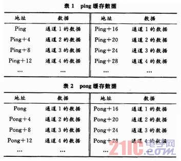
2.2 Interface Program First, you need to open 1 channel of McASP, use MCASP_open function to open 1 channel of McASP, namely DEC6713_AIC23_DATAHANDLE=MCASP_open(MCASP_DEVl, MCASP_OPEN_RESET); then use the SetupEdma function to store and continuously work on EDMA data. Definition, here the "ping-pong buffer" way, according to the idex and rld two registers to complete the data storage, the specific storage as shown in Table 1, Table 2: 
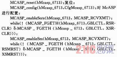
Next you need to make the McASP channel work correctly, defining the DEC6713_Mcasp_Setup function. The procedure for this function is as follows: 
Finally, you need to define the function SetInterruptsEdma() to make the entire interface program work by creating an interrupt vector table.
3 software design ideas system can be used to solidify the application in the FLAsH memory, each time the power is turned on, the DSP first downloads the program from the FALSH to the on-chip RAM. Since the DSP can wait for access to the on-chip RAM, the program is loaded into the on-chip RAM. When executed, the DSP can be guaranteed to run at full speed while enhancing the reliability of the system.
The basis for selecting the sound source localization algorithm is that the computational complexity is low or it is advantageous for hardware implementation. The algorithm can be implemented with the idea of ​​hardware. The positioning technology based on the time difference of sound (TDoA) is to first estimate the time difference of the sound by using algorithms such as GCC, LMS, EVD, etc., and then combine the spatial position of the known microphone array to determine the position of the sound source. It is not limited by the array structure and is computationally intensive, so most of the actual microphone array systems use this technology.
4 Conclusion This paper introduces the hardware design and software programming ideas based on the microphone array sound source localization system. The use of high-performance DSP device TMS320C6713 makes the processing time of the algorithm faster, especially the application of multi-channel audio serial port McASP, which makes the sound data into and out of the chip more smooth, so that the computing power of the core processing unit can be realized. Can be quickly positioned to meet the needs of a wide range of applications.
This article refers to the address: http://
Door Mat,Front Door Mat,Door Mat Outdoor,Outdoor Door Mat
Cixi Mingsheng Rubber & Plastic Co.,Ltd. , https://www.cixidoormats.com