0 Introduction With the development of IT technology, the demand for information products has become more and more vigorous, leading to the production of information products has been on a high level of development. China has become the world's manufacturing center, and information products manufacturing has contributed. However, the corresponding manufacturing equipment and production level are quite different from those of developed countries. Many high-end equipment still needs a large amount of imports from abroad. This paper presents a design scheme for an automatic plate feeder used in an electronic product manufacturing line using microcomputer technology and mechatronics technology. The hardware system, software system and simulation analysis results of the automatic board feeder are given below.
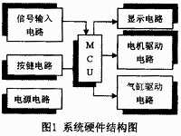
1 Hardware System The hardware system of this system is shown in Figure 1. Mainly composed of signal input circuit, button circuit, power circuit, microcomputer controller, display circuit and drive circuit.
This article refers to the address: http://

1.1 Signal Input Circuit This part of the circuit mainly completes the conditioning of the input signal and then transmits it to the central processing unit. The input signal mainly has the sending signal of the lower computer (automatic or automatic insertion machine): when the lower computer is idle, it will give a local idle signal for the upper computer to judge the working state of the machine; each sensor sends The signal: the sensor signal mainly includes the PCB board turnover box (hereinafter referred to as the turnover box) in-position signal, the turnover box clamping signal, the upper/lower limit position signal of the turnover box, and the push plate cylinder in-position signal.
1.2 Button circuit mainly has buttons for up, down, board spacing selection, start and stop. The up and down keys are mainly used to manually control the motor, and then drive and control the tote box bracket to walk along the screw. The up button is mainly used to control the elevator box tray to go up, which is generally used to determine the starting point when the new tote box is activated. The starting and ending working positions are also used to set the start and end positions of the totes that are not full of PCB boards. The board spacing selection button is to set the spacing between the PCB boards in the tote box. The default value is 1 grid. Each time the button is pressed, the spacing is increased by 1. When the starting position and spacing are set, press the start button and the system will run automatically according to the program settings. The stop button is used for motor stop control in emergency situations. Since there are not many buttons, the circuit uses a method in which a button is directly connected to an I/O port of the MCU.
1.3 Power Circuit The control, drive and execution parts of this system use DC power supply, mainly +5V, +12V, +36V. A switching power supply is used to generate the required DC power.
1.4 Microcomputer controller This is the core part of the system. Considering the needs of the system, cost performance and market share, ATMEL's 8-bit single-chip AT89C51 is used as the main controller. The AT89C51 is a low voltage, high performance CMOS 8-bit microprocessor with 4K bytes of flash memory. The device is fabricated using ATMEL high-density non-volatile memory fabrication technology and is compatible with the industry-standard MCS-51 instruction set and output pins. Combining a versatile 8-bit CPU and flash memory in a single chip is a highly efficient microcontroller that provides a flexible and cost-effective solution for many embedded control systems.
1.5 Display Circuit The display circuit mainly displays the working status of each part of the system. The display contents mainly include: working status (upstream, downlink, standby), board spacing, alarm, and the like.
1.6 Drive Circuit This part of the circuit mainly completes the drive of each actuator. The drive object mainly has screw and three cylinders. The screw payout mainly undertakes the lifting and lowering of the turnover box bracket. Considering the lifting weight and the control precision, the stepping motor is selected to drive the screw. The corresponding step control signal is generated by the central controller, and the stepping motor is driven through the pre- and power amplification circuits. The functions of the three cylinders are mainly: one is used to realize the PCB board in place, pushed forward to the lower machine entrance rail, and the other two are used to clamp the turnover box bracket on the screw to ensure the running turnover box The bracket is fixed.
2 software system software system mainly consists of main program, button subroutine, display subroutine, stepper motor drive subroutine, delay subroutine and so on. The description is as follows:
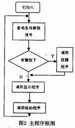
2.1 main program The main function of the main program is to cyclically call the display subroutine, button subroutine, query the status of each input signal, control each actuator according to various parameters set by the button and the state of each input signal, complete the PCB turnover box The drive control of the bracket system, as well as the orderly transmission of the PCB board, determine whether the operating state of the system is abnormal, and promptly alarm or release the alarm. The main block diagram is shown in Figure 2.

2.2 Button subroutine According to the structure of the button circuit, the independent direct reading method is adopted. The main program periodically checks the status of each relevant I/O port in priority order and saves it in a specific memory for the main program to find and use when needed.
2.3 The display subroutine timely updates the stored data of each indicator state according to the set parameters, and outputs the stored display data to each display driving circuit according to the main program calling instruction, especially when the system is abnormally operated, The drive alarm light flashes according to the system operation abnormal alarm signal.
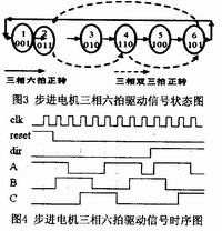
2.4 Driver The subroutine driver subroutine is primarily responsible for generating the signals required by the stepper motor driver. When the up button or down button is pressed, or the result is run according to the main program, the tote box bracket needs to be raised or lowered, and the main program calls the stepper motor driver subroutine. The stepping motor adopts three-phase six-shot working mode, and calculates the stepping motor according to the thread pitch, calculates the stepping motor step by step, and then determines the forward/reverse steps of the stepping motor under different working conditions according to the turnover box spacing. These steps are stored in the respective memories for use by the main program when calling the driver subroutine. FIG. 3 and FIG. 4 are respectively a state diagram and a timing diagram of a driving signal when the three-phase six-shot working mode of the stepping motor is performed.

3 Conclusion According to the above system hardware and software structure, the corresponding PCB circuit board and program are produced, and the mechanical processing enterprise is entrusted to produce the matching mechanical structure. Through actual operation, it shows that the system can coordinate with the automatic inserting machine to complete the task of automatically sending the board to the lower position machine.
Android is an open source mobile operating system based on Linux platform released by Google at the end of 2007, and then improved for use in netbooks and MIDs. The platform consists of operating system, user interface and application software, and is claimed to be the first truly open and complete mobile software for mobile terminals.
To put it simply, the Android system is actually a very open system. It can not only realize the functions of the most commonly used notebook computers, but also realize various directional operations like mobile phones. Moreover, it is specially designed for mobile phones. The operating system developed for equipment has advantages in system resource consumption and human-computer interaction design. It is an operating system that combines traditional and advanced advantages.
New Android Tablet,Android Tablet,New Android Tablet
Jingjiang Gisen Technology Co.,Ltd , https://www.gisengroup.com