• Operators have to squeeze 100 Gbps of traffic into existing optical fibers, which were originally designed for 10 Gbps or even 2.5 Gbps optical links.
• DWDM (Dense Wavelength Division Multiplexing) systems cannot use 100 Gbps data streams because of adjacent channel crosstalk problems.
• QPSK (quadrature phase shift keying) signals are more sensitive to noise and nonlinear phase distortion than NRZ (non-return to zero) signals.
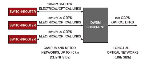
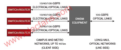
The new modulation method must be able to handle long-distance transmission. Short-distance communications, so-called clients in campus and local metropolitan area networks, do not require complex modulation because the distance is short enough to accommodate higher speeds (Figure 1). For clients, when the distance is as far as 40 km, 100 Gbps links can use four 25 Gbps channels. IEEE 802.3ba defines these data links (Reference 2). Because short-distance 100 Gbps links use four wavelengths on a single fiber, and even use 10 10 Gbps fibers on the shortest distance, more fibers may be needed to increase the existing 10 Gbps speed. It is not expensive to install additional fiber over a short distance, such as between buildings in a campus network.

Figure 1. The line end of an operator ’s data link is used for long-distance transmission between cities. Client transmission is used to connect the campus and local urban areas.
The situation with long-distance transmission is completely different. The "line end" of each service provider's network needs to transmit hundreds of kilometers. Adding fiber to compensate for the increased channel is too costly. Tektronix product engineer Pavel Zivny said: "Operators want to squeeze 100 Gbps of traffic into existing fiber, many of which were originally designed for 10 Gbps, and some are even designed for 2.5 Gbps fiber links."
It is obviously unrealistic to simply plug a 100 Gbps NRZ (non-return to zero) stream into an existing fiber. Current DWDM (Dense Wavelength Division Multiplexing) fibers use a 50 GHz separation between channels. Although this channel spacing is sufficient for a 10 Gbps data stream using NRZ modulation, it is too narrow for a 100 Gbps NRZ stream. Mike Schnecker, LeCroy's business development manager, said: "You can't directly add a 100 Gbps stream to the carrier." The reason is that for a 100 Gbps NRZ signal, the width of each bit is only 10 ps.
Hiroshi Goto, Anritsu ’s Optical Product Specialist, said: “Due to crosstalk problems in adjacent channels, 100 Gbps data streams cannot be used in DWDM systems. PMD (Polarization Mode Dispersion) and CD (Dispersion) prevent this. There are too many. Distortion. Pulse distortion and overlap. "
To solve this problem, OIF (Optical Interconnect Forum) recommends the use of complex modulation so that more bits can be loaded per second per second using existing fiber. OIF proposes to use QPSK (quadrature phase shift keying) and dual polarization to achieve 100 Gbps traffic on a single wavelength. QPSK is common in digital RF communications, but it is new to optical fiber communications.
A 100 Gbps link contains two polarizations—TE (transverse electric) and TM (transverse magnetic), two 50 Gbps streams, which are transmitted on two orthogonal polarization planes. Each 50 Gbps stream contains 25G symbols / second. QPSK modulation encapsulates 2 bits into one symbol. Because the QPSK signal is transmitted on two polarization planes, it can be called DP-QPSK (dual polarization QPSK), or PM-QPSK (polarization mode QPSK); both terms are often used and can be interchanged. This article uses DP-QPSK when referring to dual polarization and QPSK when referring to single polarization.
Complex modulation
Figure 2 shows the modulation process. A single 100 Gbps stream is divided into TE and TM polarizations. This step produces two carriers of the same frequency. Then, each carrier is subjected to I / Q (in-phase / quadrature) modulation to obtain two streams of 25G symbols / second. The total is 100 Gbps, but the actual data rate is slightly higher (see Attachment 1 "What's in a G"). The polarity splitter in Figure 2 appeared before the QPSK modulator. Some transceiver designs may put the I / Q modulator first, and then separate the modulated signal into two polarities.

Figure 2. A 100 Gbps transmitter splits a laser beam into two polarization planes and then modulates four 25 Gbps data streams on a single wavelength fiber.
QPSK modulation is to respond to incoming code pairs (00, 01, 10, 11), phase shift the optical carrier, and place 2 bits in each symbol. Each symbol represents 2 bits. The receiver demodulates each symbol into 2 bits to obtain a 50 Gbps digital data stream. In addition, bits are pre-coded before modulation and decoded after modulation (Reference 3). Then, the receiver demodulates and decodes the incoming DP-QPSK signal, generating four 25 Gbps electrical signals.
The number of bits carried per symbol in the QPSK signal is twice that of the NRZ signal. Therefore, when the signals generated by the two modulations pass through the optical fiber, the degree of degradation is also different. Peter Andrekson, Director of EXFO Sweden, explained that QPSK signals are more sensitive to noise and nonlinear phase distortion than NRZ signals. He said: "Because of the high sensitivity to noise, QPSK modulated signals require more power than NRZ signals."
However, QPSK signals also have an important advantage over NRZ signals. That is, at the same bit rate, they are less sensitive to errors from dispersion and group delay. This is because a UI (unit interval) width of 100 Gbps data is 10 ps. Since the line transmission uses four 25 Gbps channels, each symbol is 40 ps wide, and it has a low bandwidth.
A 40 ps wide symbol with a 25G symbol / second stream is shorter and requires a higher bandwidth than a 10 Gbps, 100 ps wide NRZ signal. Therefore, a 25G symbol / second signal is more sensitive to dispersion errors than a 10 Gbps NRZ signal, but it is less sensitive to degradation than a 100 Gbps NRZ signal. Andrekson explained: "At a certain code rate, there is a compromise between complexity and SNR (signal-to-noise ratio) as well as dispersion tolerance and hardware bandwidth."
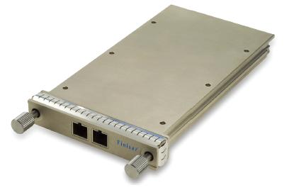
DP-QPSK technology is so new that there is no transceiver module for the line side. Finisar senior technician Chris Cole explained that the transceiver module on the line side is larger than the client module (Figure 3), and a multi-entity agreement is now being determined (Reference 4). Cole pointed out that designers can even implement the line-end transceiver as a line card instead of a module.

Figure 3, the optical transceiver used for client transmission is based on a CFP multi-source protocol (provided by Finisar) for a line card size and electrical connection.
Test also needs to change
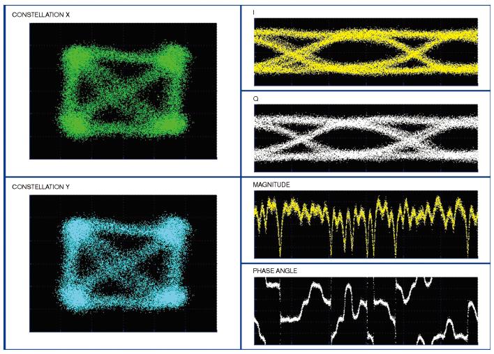
The transfer from NRZ to DP-QPSK modulation brings a constellation diagram for the fiber front-end test. Although constellation diagrams are common in RF wireless transmission, they are still new to optical communications. The first measurement made on a QPSK transmission is the constellation diagram. The constellation diagram provides information about the integrity of the transmitted signal. Both dispersion and nonlinearity can cause signal degradation, resulting in distortion. Figure 4 shows a constellation of two polarities in a DP-QPSK signal. In Figure 4, the points of the constellation are clearly visible, but after too much distortion, they may become blurred.
The two waveforms in the lower right corner of Figure 4 show the amplitude (top) and phase (bottom) of the QPSK-modulated signal. Note the apparent discontinuity in the phase angle diagram. They originate from the phase shift, because QPSK modulation is the coding of pairs of bits.
When testing optical DP-QPSK signals, optical modulation can be used, or an optical signal analyzer can be used. These instruments can generate a constellation diagram, decode it into an electronic data stream, and display it as an eye diagram. Companies serving this market include Agilent Technologies, Anritsu, EXFO, and Optametra. Optametra's products use Tektronix oscilloscopes.
Finisar's Cole said: "There is no test specification for 100 Gbps long-range light waves, so test equipment manufacturers must communicate with optical module manufacturers to see what they need to measure. Each company has different needs." It is pointed out that the test equipment must be able to support 28G and 32G symbols per second. "There is now a DP-QPSK test system that can run at 22G symbols / sec for 40Gbps links, but the new equipment must be able to run at 28G and 32G symbols / sec to support 100 Gbps
link. "
The test of the receiving end of the optical transceiver is even more unresolved, because there is no test specification for a stressed-receiver. Cole said that the test equipment must be able to generate DP-QPSK signals, but this requirement may produce some control defects, such as dispersion and polarization mode dispersion. These defects can cause the TE and TM carriers to rotate as they pass through the fiber. After demodulation and decoding, these defects will definitely produce a stress eye diagram, so once it becomes an electronic form, engineers can measure it.
Figure 4 also shows two eye diagrams (upper right corner), showing two 25Gbps channels with one polarization. Cole said: "You must also look at the margin, jitter, and extinction ratio of the eye mask; this is the same as the 10 Gbps link."

Figure 4. The constellation diagram will become a mainstream tool (provided by EXFO) for analyzing DP-QPSK modulated signals.
Now, engineers can analyze the eye diagram with an oscilloscope and BER (Bit Error Rate) tester. Some engineers use high-bandwidth oscilloscopes to capture DP-QPSK signals. LeCroy's Schnecker said: "Because of the modulation, the signal at the receiver looks like noise. The signal is no longer repetitive, so you need a real-time oscilloscope." Zivny of Tektronix has worked with some engineers in DP-QPSK A real-time oscilloscope has been used on the signal. A four-channel oscilloscope can see all four decoded and demodulated data streams with high time base correlation.
The engineers who developed the DP-QPSK transceiver also used a BER tester to generate a 25 Gbps data stream for each I and Q phase of a QPSK signal. They also use a BER tester to measure the BER on the modulated and coded signal. The BER testers of Agilent Technologies and SyntheSys Research can measure up to
28 Gbps data rate.
In the next few years, the industry will continue to develop
100 Gbps line-side transmission. Test specifications will also appear, and optical module manufacturers will collaborate with test equipment manufacturers and standardization groups to identify test issues and develop test routines and equipment
Attachment 1: What's in a G?
The terms "100G", "40G" and "25G" all refer to the data traffic in an optical link. Due to formatting and FEC (forward error correction), the actual data stream is higher than the value indicated by the number.
For example, the data rate of a 100 GbE (Gigabit Ethernet) transmission is actually 103.125 Gbps, but the data traffic is 25 Gbps. Therefore, each 25 Gbps channel actually carries 25.78125 Gbps (26 Gbps) for the client. Therefore, if a test equipment manufacturer claims that its product has a speed of 26 Gbps, it means that the product covers a data rate of 25.78125 Gbps. In addition, for an Ethernet client network, a data rate of 27.739 Gbps (28 Gbps) is also being considered.
For line-end networks, long-distance transmission links require additional FEC. The 100 Gbps link line rate with 7% FEC is approximately 112 Gbps, which translates to approximately 28 Gbps per channel. According to the "100G Ultra Long Distance DWDM Framework Document" of the Optical Interconnection Forum, the exact rate has not been determined (Reference A). These transmissions can also use a higher 20% FEC overhead, so that the code rate will increase to approximately 32 Gbps.
Breze Stiik box pro 5000 Disposable Vape wholesale from china factory,welcome contact
Breze Stiik box pro 5000
Shenzhen Ousida Technology Co., Ltd , https://www.osdvape.com