Generally speaking, grounding, shielding and filtering are the three most common measures to suppress electromagnetic interference. This article mainly introduces one of the methods of filtering power filters. I hope to help you better understand the filter circuit.
Power filterThe power filter is a filter circuit composed of capacitors, inductors and resistors, also known as "power EMI filter" or "EMI power filter", a passive two-way network, one end of which is the power supply and the other end is the load . The principle of the power filter is one kind-impedance adaptation network: the greater the impedance adaptation between the input and output sides of the power filter and the power and load sides, the more effective the attenuation of electromagnetic interference. The filter can effectively filter out the frequency point of a specific frequency in the power line or the frequency other than the frequency point to obtain a power signal of a specific frequency, or eliminate a power signal of a specific frequency.
Power filter adaptation principleThe commonly used filter circuits of power filters include passive filter and active filter. The main forms of passive filtering are capacitive filtering, inductive filtering and compound filtering (including inverted L-type, LC filtering, LCÏ€-type filtering and RCÏ€-type filtering, etc.). The main form of active filter is active RC filter, also known as electronic filter. The magnitude of the pulsation component in the direct current is represented by the pulsation coefficient S. The larger the value, the worse the filtering effect of the filter.
Ripple coefficient (S) = the maximum value of the fundamental wave of the AC component of the output voltage / the DC component of the output voltage
The principle of the power filter is an impedance adaptation network: the greater the impedance adaptation between the input and output sides of the power filter and the power and load sides, the more effective the attenuation of electromagnetic interference.
The specific working principle is as follows: After the alternating current is rectified by the diode, the direction is single, but the magnitude (current intensity) is still in constant change. This kind of pulsating DC is generally not directly used to power the radio equipment. In order to turn the pulsating DC into a smooth DC waveform, it is necessary to do some "fill in and out" work, which is filtering. In other words, the task of filtering is to reduce the fluctuation component in the output voltage of the rectifier as much as possible and transform it into a near constant and stable direct current.
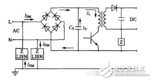
According to the electromagnetic disturbance characteristics of the power port, the power supply EMI noise filter is a passive low-pass filter, which transmits the AC power to the power supply without attenuation, and greatly attenuates the EMI noise introduced with the AC power, and at the same time can effectively suppress The EMI noise generated by power supply equipment prevents them from entering the AC grid to interfere with other electronic equipment.
The typical structure of the power filter is shown in the figure below. This is a passive network structure, which is suitable for both AC and DC power supplies and has two-way suppression performance. Inserting it between the AC power grid and the power supply is equivalent to adding a blocking barrier between the EMI noise of the two. Such a simple passive filter has the effect of suppressing noise in both directions. Widely used in equipment.
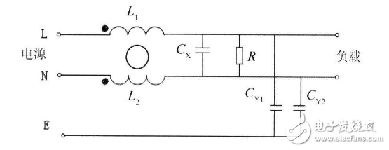
Basic structure of power filter
In the figure, Cx is a differential mode capacitor, generally called X capacitor, the capacitance should be 0.01-2.22μF, CY1 and CY2 are common mode capacitors, generally called Y capacitors, the capacitance is about a few nanofarads (nF) to a few Ten Nafa. The capacitance of C3 and C4 should not be selected too large, otherwise it will easily cause the danger of leakage of the filter and even the case. L is a common mode choke coil, which is a pair of coils wound on the same ferrite ring in the same direction, and the inductance is about several millihenries (mH). For the common mode interference current, the magnetic fields generated by the two coils are in the same direction, and the common mode choke coil exhibits a larger impedance, thereby playing the role of attenuating the interference signal; and for the differential mode signal (here, the low-frequency power supply current ), the magnetic fields generated by the two coils cancel out, so the power transmission function of the circuit is not affected.
The power filter is designed for the characteristics of electromagnetic disturbance at the power port. It is generally a frequency selective two-port network composed of inductors, capacitors, resistors or ferrite devices. In fact, it is a kind of filter, which is called according to the working principle. It is a reflective filter. It can provide high series impedance and low parallel impedance in the filter stop band, making it seriously mismatched with the impedance of the noise source and the load impedance, thereby emitting undesired frequency components back to the noise source.
When we choose a power filter, we should mainly consider three indicators: firstly voltage and current, secondly insertion loss, and finally structure size. Since the inside of the filter is generally potted, the environmental characteristics are not a major issue. However, the temperature characteristics of all potting materials and filter capacitors have a certain impact on the environmental characteristics of the power filter.
Power filter application analysis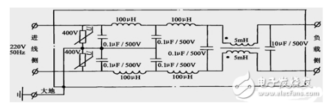
The 100H inductor and 0.1F capacitor in the picture form a high-frequency filter, which is used to absorb high-frequency noise interference in the short and medium wave bands conducted from the power line; the two symmetrical 5mH inductors in the picture are wound on both sides of the same iron core , Inductance windings with equal turns are called common-mode inductors, which are used to absorb harmonic interference caused by power waveform distortion; the varistor in the picture is used to absorb surge voltage interference caused by lightning strikes. The internal circuit of the AC power filter.
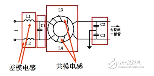
Common mode inductance in power filter
When the 50Hz current flows through the common mode inductor, since the magnetic fields generated by the incoming line and the outgoing line are in opposite directions, they cancel each other and will not produce a voltage drop. However, the common mode inductance has a greater inductance to common mode interference.
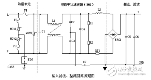
Lightning protection circuit: When there is a lightning strike and high voltage is generated and imported into the power supply through the power grid, a circuit composed of MOV1, MOV2, MOV3: F1, F2, F3, FDG1 is used for protection. When the voltage applied to both ends of the varistor exceeds its working voltage, its resistance is reduced, causing high-voltage energy to be consumed on the varistor. If the current is too large, F1, F2, and F3 will burn out the protection circuit.
Input filter circuit: The double π-type filter network composed of C1, L1, C2, and C3 is mainly to suppress the electromagnetic noise and clutter signal of the input power supply, prevent interference to the power supply, and also prevent the high-frequency clutter generated by the power supply itself. Power grid interference. When the power is turned on, C5 needs to be charged. Due to the large instantaneous current, adding RT1 (thermistor) can effectively prevent inrush current. Because the instantaneous energy is all consumed in the RT1 resistance, after a certain period of time, the resistance of RT1 decreases after the temperature rises (RT1 is a negative temperature coefficient component). At this time, it consumes very little energy, and the subsequent circuit can work normally.
Rectifier filter circuit: AC voltage is rectified by BRG1 and filtered by C5 to obtain a relatively pure DC voltage. If the C5 capacity becomes smaller, the output AC ripple will increase.
Principle of DC input filter circuit

Input filter circuit: The double π-type filter network composed of C1, L1, and C2 is mainly to suppress the electromagnetic noise and clutter signal of the input power supply to prevent interference to the power supply, and at the same time prevent the high-frequency clutter generated by the power supply itself from interfering with the grid . C3 and C4 are safety capacitors, and L2 and L3 are differential mode inductors. R1, R2, R3, Z1, C6, Q1, Z2, R4, R5, Q2, RT1, C7 form an anti-surge circuit. At the moment of starting, Q2 does not conduct due to the presence of C6, and the current forms a loop through RT1. When the voltage on C6 is charged to the regulated value of Z1, Q2 turns on. If C8 leaks or the subsequent circuit is short-circuited, the voltage drop generated by the current on RT1 at the moment of starting will increase, and Q1 will be turned on so that Q2 will not conduct without the gate voltage, and RT1 will be burned in a short time. Protect the subsequent circuit.
ConclusionWhen analyzing the working principle of the power filter, the main use of the capacitor's "through-pass" characteristic, or charging and discharging characteristics, that is, the filter capacitor is charged when the rectifier circuit outputs a unidirectional pulsating DC voltage, when there is no unidirectional pulsating DC voltage When outputting, the filter capacitor discharges to the load. So far, that's it for the introduction of power supply filters. Please correct me if there are any deficiencies.
Yuchai ≥1000KW Diesel Generator
Yuchai ≥1000Kw Diesel Generator,Yuchai Shanghai Genset,Yuchai Shanghai Power Generator,Yuchai Power Generator Set
Shanghai Kosta Electric Co., Ltd. , https://www.generatorkosta.com