1 Introduction
Electric vehicles have entered millions of households in recent years. They are mainly two-wheeled electric bicycles. They are low-carbon and environmentally friendly. They have a wide range of applications. They include more types of vehicles, with three-wheeled and four-wheeled low-speed vehicles. There are four-wheel EV models, there are also electric buses and electric trucks, sightseeing cars, etc. The single-applied approach is basically the same. The three- and four-wheeled electric vehicles basically have little demand for sensors, and they are generally more The use of shunts or Hall sensors that are relatively simple or low-end, there are many domestic manufacturers are their products with a very simple and simple way out, the overall safety of such a low-speed car can not be guaranteed, this article mainly introduces Is the selection and use of current sensors based on electric buses and household electric cars
2, the principle of Hall current sensor
At present, current sensors used in electric vehicles are basically open-loop current sensors. Previously, the current sensors used in electric vehicles were closed-loop current sensors because of the high accuracy of the closed-loop current sensors and the faster response time. Compared with open-loop current sensors, The current sensor has great advances in cost-effectiveness, structure size, and high and low temperature characteristics, and has greatly increased in reliability. This is mainly due to the current internal structure of the current sensor is relatively simple.
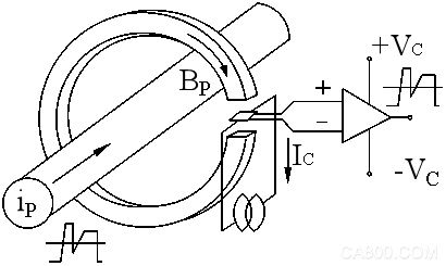
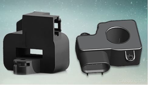
The open-loop Hall current sensor is based on the direct-measurement Hall principle, which is the open-loop principle (also known as the Hall test only). The magnetic flux generated by the primary current IP is collected by the high-quality magnetic core in the magnetic circuit, and the Hall element is fixed. In a small air gap, the magnetic flux is linearly detected. After the Hall voltage output from the Hall device is processed by a special circuit, the secondary side outputs the output voltage following the waveform of the primary side. This voltage can accurately reflect the primary current. The change. The schematic and appearance are as follows:
Hall sensor characteristics
Hall sensor whether it is open-loop or closed-loop principle, the basic performance difference is not, the basic advantages are:
A. Fast response time
B, low temperature drift
C, high measurement accuracy
D, small size
E, strong overload
3, the type of electric vehicle current sensor
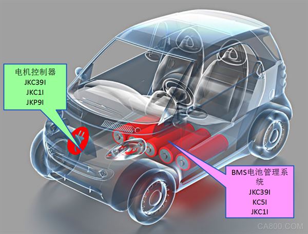
Electric vehicle sensors are mainly divided into two parts, BMS battery management system and motor controller. Some of the current sensors in these two systems can be compatible with each other, depending on the designer's concept and the needs of the terminal market. as follows:
BMS battery management system
According to the current use requirements, the applicable models are JKC39I, JKC5I, and JKC1I. Among them, JKC39I is a single-supply single-range current sensor and needs to provide 5V power supply; JKC1I current sensor is a dual-power dual-range current sensor and needs to provide DC ±12-15V power supply. The above two models are more widely used in low- and medium-speed vehicles, and the application of the JKC39I in the unopened market will be even greater, because the reliability is higher than that of the JKC1I.
In addition, JKC5I is a single-supply dual-range current sensor, also requires a single power DC +5V power supply, there are two cores, two Hall components and two magnetic core sheath, when the current is less than a certain current value The sensor automatically switches to the first range. When it is greater than this current value, it automatically switches to the second channel for measurement. This is mainly to ensure the accuracy of the current sensor.
Currently, one current sensor in a BMS battery management system is basically used. Unless the customer has different requirements in the high-voltage electromechanical box, a current sensor may be added. Increasing the battery current will only increase the hard cost of the electric vehicle.
Motor Controller Application
At present, there are essential differences in the design and use of motor controllers. Low-speed vehicles generally detect three-phase currents in motor controllers. JKC39I, JKC1I, and JKP9I are applicable to these three series. There is a certain difference between the technical parameters and the installation method. Among them, the JKC1I has more applications in low-speed vehicles and electric buses. The main reason is that such sensors are relatively cost-effective and belong to the general market, but in terms of overall reliability. No other series is higher.
In addition, JKP9I and JKC39I are the current domestic applications of domestic electric cars, mainly because these two series of current sensors have a simple structure and do not require a PCB processing circuit. All detection and processing are completely focused on the Hall chip. The reliability of the chip is very high. High, a PCB is needed to hold the Hall element fixed and a magnetic ring is needed to sense the magnetization.
The above is a brief introduction of the current part of the domestic electric vehicle current sensor.
4. Comparison and structure of current sensors
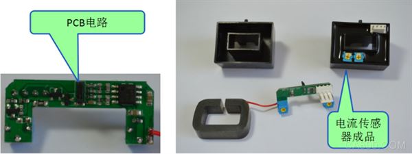
Note: JKC1I current sensor structure diagram
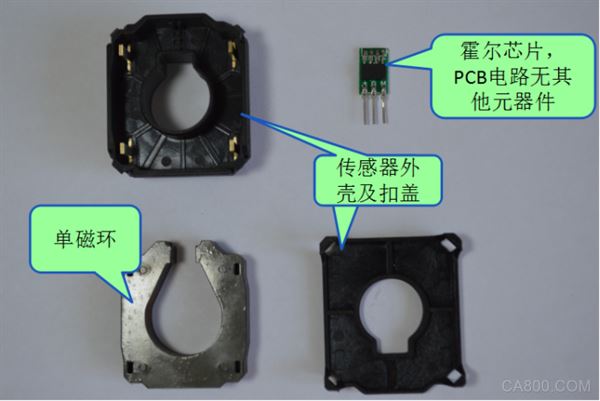
Note: JKP9I current sensor structure diagram
According to the above dismantling diagram, it can be seen that although JKC1I has a larger market application than other products, there are about 20 electronic components on the PCB circuit. Each additional component will reduce the overall reliability of the current sensor. In contrast, the JKP9I circuit is very simple. It consists of a Hall chip and a magnetic core. The construction is very simple and the reliability is greatly increased. After testing, only the high temperature of 170°C will cause both the core and the chip to fail simultaneously. However, if it reaches 170°C, it is estimated that other components inside the vehicle controller have partially failed, so the current sensor failure rate is very low.
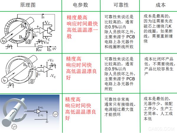
Note: Comparison of closed-loop current sensors, open-loop current sensors, and electric vehicle current sensors
5, the current sensor needs to pay attention when selecting and using:
A, need to pay attention to wear the sensor hole size can ensure that the wire can pass through, if it is measuring cable, you need to pay attention to the cable after the end of the line, the product maintenance, the sensor is a good removal, the best choice to use the copper row, that is beautiful and easy Maintenance installation
B. Need to pay attention to whether the space structure is satisfied;
C. When wiring, pay attention to the bare conductive part of the Terminal Block and try to prevent ESD impact. Engineers with professional construction experience are required to perform wiring operation on this product. The connection wires of the power supply, input, and output must be connected correctly. They must not be misplaced or reversed. Otherwise, the product may be damaged.
D, product installation environment should be non-conductive dust, corrosive
E. Pay attention to the way of threading. Do not let the measured conductor be filled with the sensor's perforation as much as possible. If it cannot be achieved, let the conductor under test remain centered and fixed. This will reduce the position error caused by shaking.
6. Concluding remarks
The policy subsidy for new energy vehicles has been declining year by year, and the market competition has become increasingly fierce. Today, how to reduce the hard cost of products, ensure product reliability, and reduce production cycle is a long-term task that all manufacturers need to do. The current sensors are used as automotive BMS and control. The important core components in the device play a vital role. As a supplier, we understand the importance of this product and believe that we can do our best! Specific product information can click to understand
Description of Antenk's Slim D-Sub Connector
D-Sub Connector Slim is a space-saving D-sub Socket Connector with an 8.54mm depth. The slim 8.54mm depth reduces the board mounting area by 33% as compared with standard models. The Slim Profile D-Sub Connectoroffering includes D-sub sockets with nine right-angle DIP terminals and a mounting board thickness of either 1.6 mm or 1.0 mm (from difference in lock pin structure). RoHS compliant, Slim D-Sub Connector offers a 3A rated current, 300VAC rated voltage, and an insertion durability of 100 times within an operating temperature range of -25º to 105ºC.
Features of Antenk's Slim D-Sub Connector
Board mounting area is reduced by 33% (compared with standard models) using a depth of 8.4mm
D-sub sockets with nine right-angle DIP terminals
Mounting board thickness of either 1.6mm or 1.0mm (from difference in lock pin structure)
RoHS Compliant
Applications of Antenk's Slim D-Sub Connector
Factory Automation
Machine Tools
Power SuppliesMedical Tools
Test & Measurement
LSI/FPD Manufacturing Systems
Information Transmission Tools
Security Tools
Industrial Tools
Slim D SUB Connector,High Density D-Sub Connector Slim, Solder type D-Sub Connector Slim,Right Angle D SUB Connector Slim, slim profile 90°- SMT D SUB Connector,9 15 25pin slim profile 90°- THT D SUB Connector
ShenZhen Antenk Electronics Co,Ltd , https://www.atkconnectors.com