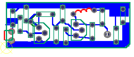
A pocket transmitter introduced to you here is very suitable for beginners. The circuit is simple and easy to manufacture, the cost is low, the output power is no more than 5-8mW, and the launch range is up to 300 meters in the house area. An ordinary FM radio is used. Receive, showing its sensitivity and clarity, the most challenging part of circuit design is the ability to transmit with only a 3V power supply and a half-wave antenna. In addition, because the circuit requires very few parts, it can be placed in a matchbox (larger than the domestic matchbox). As a bug, it is ignorant and unintelligible, but it is not limited to this. In terms of use, it can be placed in the baby room, gate or corridor to monitor the actual situation, and can also be used as a night security device.
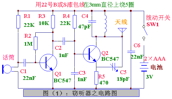
The current consumption of the circuit is less than 5mA, and it can work continuously for 80 to 100 hours with two dry batteries. The circuit is very stable under normal operation, and the frequency drift is very small. Test: After 8 hours of operation, it is not necessary to re-calibrate the receiver. The only effect on the output frequency is the condition of the battery. When the battery ages, the frequency changes slightly. With this production, learn about FM transmission, you can understand its superiority, especially it produces a very high quality signal without noise, even with low power transmission, it is easy to get a good range. Circuit Operation From the circuit of Figure (1), there are two stages, a primary audio amplifier and a primary RF oscillator. There is actually a FET hidden in the electret microphone. If you like it, it can be regarded as one level. The FET amplifies the capacitance change of the front diaphragm of the microphone. This is the reason why the resident microphone is very sensitive. The audio amplifier stage is operated by its emitter transistor Q1 with a gain of about 20 to 50, and the amplified signal is sent to the base of the oscillation stage. The oscillating stage Q2 operates at a frequency of about 88 MHz, which is regulated by an oscillating coil (5 turns total) and a 47pF capacitor. This frequency is also determined by the transistor, the 18pF return capacitor, and a few bias components, such as 470Ω emitter resistors. And 22K base resistance. 

Pv Ribbon Intelligent Factory,Solar Intelligent Workshop,Solar Welding Strip Production,Sunlight Solar Bus Bar Production Machinery
Jiangsu Lanhui Intelligent Equipment Technology Co., Ltd , https://www.lanhuisolar.com