The furnace temperature control system is a relatively common and typical process control system. The heating reactor consists of four valves: exhaust valve, feed valve, nitrogen valve, bleed valve, four sensors: pressure sensor, temperature sensor, upper Liquid level sensor, lower level sensor, boiler, heater and heating contactor. The heating reaction furnace is an important equipment commonly used in industrial production. In the past, it only relied on manual operation. There were often problems in which feedstock, temperature, pressure and other conditions could not be effectively controlled. The quality of the product was unstable, resulting in waste of raw materials and economic losses to the company. . Therefore, the programmable controller PLC has the characteristics of high reliability, strong function, flexible control, simple programming and convenient use, and has become the preferred control device in the industrial field. The use of automatic control system can effectively improve the safety of production, greatly reduce the incidence of accidents, and improve production efficiency, so that the use of raw materials is maximized. In the system, the mature programmable logic controller with technology comparison is adopted on the hardware. The switch quantity and analog input module of PLC are adopted to realize the acquisition of analog quantity; the method uses the feedback commonly used in process control. And the cascade control method ensures the stability and security of the system.
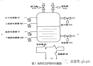
Design tasks and requirements
1. According to the above heating process of the heating reactor, the PLC control program is programmed, and the I/0 electrical interface diagram is drawn.
2. Debugger, simulation run.
Design
1. Process and control requirements
1. Feed control
1 Detect whether the lower surface SQ2, the furnace temperature ST, and the furnace internal pressure SP are all less than a given value (the setting values ​​are all logical quantities).
2 If it is less than the given value, open the exhaust valve YVl and the feed valve YV2.
3 When the liquid level rises to the upper liquid level SQl, the exhaust valve YVl and the feed valve YV2 should be closed.
4 delay 20s, open the nitrogen valve YV3, nitrogen into the reactor, the pressure inside the furnace rises.
5 When the pressure rises to a given value, that is, SP = "1", the nitrogen valve is closed.
2. Heating reaction control
1 AC contactor KM is energized, and the power of the heater heater EH is turned on.
2 When the temperature rises to a given value (ST: "1"), the heater power is turned off, and the AC contactor KM loses power.
3 delay 10min heating process is over.
3. Vent control
1 Open the exhaust valve to lower the pressure in the furnace to the predetermined minimum value (SP: "0").
2 Open the bleed valve and close the bleed valve and vent valve when the solution in the furnace drops to the lower level (SQ2 = “0â€). The system returns to its original state and is ready to enter the next cycle.
2. Working principle of heating reactor
The basic structure of the heating reactor temperature control system is shown in the figure below. It consists of four parts: PLC main control system, solid state relay, heating furnace and temperature sensor.
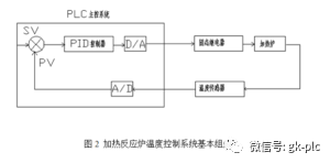
The temperature control process of the heating furnace is: first, the temperature sensor converts the temperature of the heating furnace into a voltage signal, and the A/D inside the PLC main control system converts the incoming voltage signal into a digital quantity recognizable by the PLC, and then the PLC gives the system a given The temperature value is compared with the feedback temperature value and processed by the PID operation, and a control signal is input to the input end of the solid state relay to control whether the output end of the solid state relay is turned on or not to start heating or stop heating.
3. Table of input and output equipment for heating the reactor:
According to the requirements of the automatic control system of the heating reactor, 6 input points and 5 output points are required, for a total of 11 I/O points.
| input device | Output device |
| start up button | Heating contactor |
| stop button | Vent |
| Upper level sensor | Feed valve |
| Lower level sensor | Nitrogen valve |
| Pressure sensor | Drain valve |
| Temperature sensor |
Table 1
4. I, O address table:
There are 6 input signals for heating the reactor, and there are 5 output signals, all of which are switching quantities. The input and output address layout table is shown in the figure below.
| variable: | X1 | X2 | X3 | X4 | Y1 | Y2 | Y3 | Y4 | Y5 | T0 | T1 | SB1 | SB2 | K |
| Initial value: | 0 | 0 | 0 | 0 | 1 | 1 | 1 | 1 | 1 | 0 | 0 | 0 | 0 | 0 |
| Types of: | Switch input | Switch input | Switch input | Switch input | Switch output | Switch output | Switch output | Switch output | Switch output | Switch input | Switch input | Switch input | Opening amount input | Numerical value |
| Features: | Lower level detection | Furnace temperature | Upper level detection | Furnace pressure | Vent | Feed valve | Nitrogen valve | Drain valve | Heating furnace power supply | Timer time to | Timer start | start up button | start up button | Timer time |
Table 2
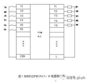
5 .I, O electrical interface diagram:
According to the I, O address layout table, the I, O electrical interface diagram is shown below.
6. Control flow chart:
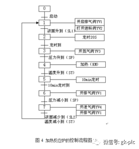
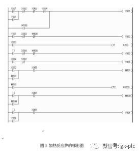
The functions realized by the heating reactor control system, combined with the PLC, can be designed as shown in the system control flow. When the start button SB1 is pressed, the system operates; when the stop button SB2 is pressed, the system stops.
The first stage: feeding control, detecting the lower level SL1, the furnace temperature ST, whether the furnace pressure SP is less than a given value (both "0"), if YV1 and the feed valve YV2. When the liquid level rises to the upper liquid level setting value, SL2=1, the exhaust valve YV1 and the feed valve YV2 should be closed. With a delay of 10S, the nitrogen valve YV3 is turned on, and nitrogen enters the reaction furnace, and the pressure in the furnace rises. When the pressure rises to a given value, ie SP=1, the nitrogen valve is closed. The feeding process ends.
The second stage: heating reaction control, turning on the reactor power supply KM, and starting to warm the reaction furnace. When the temperature rises to a given value (in this case, the signal ST = 1), the heating power is turned off. The delay is 10S and the heating process ends.
The third stage: bleed control, open the exhaust valve YV1, so that the pressure in the furnace drops below a given value (SP = 0 at this time). Open the bleed valve YV4. When the solution in the furnace drops below the lower level (SL1=0 at this time), close the bleed valve YV4 and the vent valve YV1. The system is restored to its original state and ready to enter the next cycle.
According to the requirements of the electric control system of the heating reaction furnace, the design control system includes a total of 6 input signals including the manual: the lower liquid level detection signal X1, the liquid level detection signal X3 on the furnace temperature X2, the furnace pressure X4; X5 , X6 is a manual automatic switching button. The five output signals Y1—Y5 of the PLC represent the exhaust valve, the feed valve, the nitrogen valve, the relief valve, the heating of the reactor, and the timers T1 and T2 are 0.1S timers.
The heating reaction furnace control system is mainly composed of the monitoring part of the upper computer, the PLC system, the signal detection part and the execution part. The online real-time recording, monitoring and display data, the real-time status of the equipment is transmitted, and the system real-time control commands are accepted and executed. By controlling the opening and closing of the solenoid valve, the requirements of system control are met.
Hanzhong Hengpu Photoelectric Technology Co.,Ltd , https://www.hplenses.com