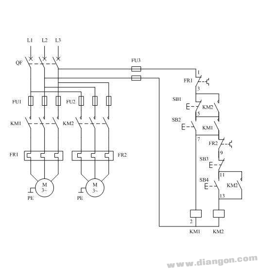
Schematic diagram of sequential starting and sequence stop circuit of two motors

The sequential start and stop control circuit is a control method that can be started after another device starts up. It is often used for control between the primary and secondary devices. As shown in the figure above, when the contact device KM1 of the auxiliary device is started, the main device The contactor KM2 can be started, the main device KM2 does not stop, and the auxiliary device KM1 cannot be stopped. However, the auxiliary equipment should stop running during a certain period of operation (such as FR1 action), and the main equipment will stop running.
work process:
1. Close the switch QF to introduce the power of the line.
2. According to the auxiliary device control button SB2, the contactor KM1 coil is electrically connected, the main contact closes the auxiliary device, and the KM1 assists the normally open contact to achieve self-protection.
3. Press the main device control button SB4, the contactor KM2 coil is electrically connected, the main contact closes the main motor to start running, and the KM2 auxiliary normally open contact is closed for self-protection.
4. Another auxiliary normally open contact of KM2 shorts SB1, which makes SB1 lose control and cannot stop auxiliary device KM1 first.
5. When stopping, only press the SB3 button to make the KM2 coil lose power auxiliary contact reset (contact disconnect), the SB1 button will work.
6. The overcurrent protection of the main motor is completed by the FR2 thermal relay.
7. The overcurrent protection of the auxiliary equipment is completed by the FR1 thermal relay, but after the FR1 action, the control circuit is completely powered off, and the main and auxiliary equipments are completely stopped.
Common malfunctions;
1, KM1 can not achieve self-locking:
Analysis and processing:
1. The auxiliary contact of KM1 is connected incorrectly, and it is connected to the normally closed contact. KM1 is normally closed and closed, so there is no self-locking.
Second, KM1 normally open and KM2 normally closed position connected wrong, KM1 suction type KM2 has not been sucked, KM2 assisted normally open when disconnected, so KM1 can not be self-locking.
2, can not start KM2 in sequence can be started first;
Analysis and processing:
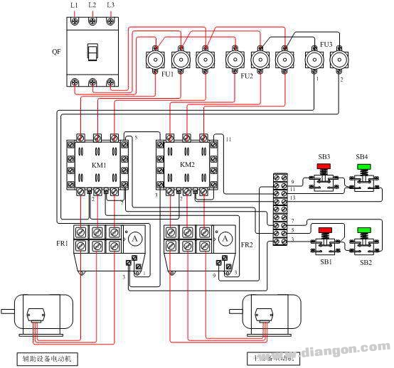
KM2 starts first to indicate that the control circuit of KM2 has power. Check that FR2 has power. This may be the 7th line of the upper end of FR2 contact. It is wrongly connected to the position of line 3 of the upper port of FR1. This makes KM2 not controlled by KM1. It can be started directly.
3, can not stop KM1 can stop first;
Analysis and processing:
KM1 can stop this to indicate that SB1 is functioning, and the connected KM2 normally open contact does not work. There are two reasons for the analysis.
1. The KM2 auxiliary normally open contact connected to both ends of SB1 is not connected.
2. The KM2 auxiliary contact connected to both ends of SB1 is connected to the normally closed contact.
4, SB1 can not stop;
Analysis and processing:
The inspection circuit found that the KM1 contactor used two auxiliary normally open contacts. KM2 only used one auxiliary normally open contact. The two ends of SB1 are not normally open of KM2 but normally open of KM1. Since KM1 is normally open and closed after self-locking So SB1 doesn't work.
Schematic diagram of sequential starting and sequence stop circuit wiring of two motors

Engine Parts oil tube,Engine Parts water pipe,Engine Parts exhaust pipe,Engine Parts Rubber Pipe
Chongqing LDJM Engine Parts Center , https://www.ckcummins.com