Digital signal is the main signal form in current digital electronic products, usually single-ended signal, CMOS or TTL level. The digital signal we observe is generally a series of pulses with different widths, and the clock signal is usually a rectangular pulse with the same pulse width.
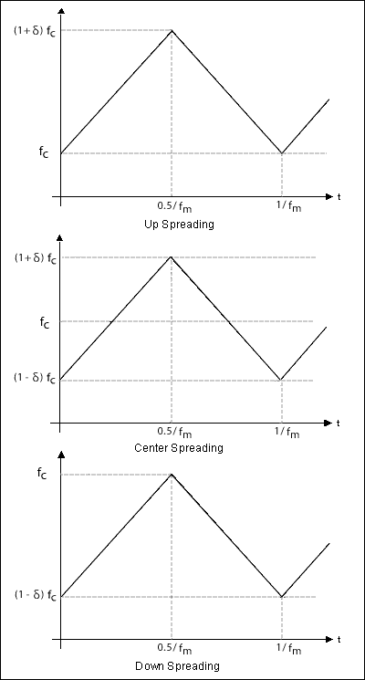
The frequency components of the digital signal and the CLK signal include higher-order harmonics. The signal itself and its harmonics together produce electromagnetic interference (EMI) within and between electronic systems. A simple and effective way to reduce EMI is to make the CLK frequency jitter [1, 2]. This application note introduces spread-spectrum CLK (MAX9492) and provides a method for quickly calculating EMI suppression using clock parameter specifications. Spread Spectrum CLK: Definition and Measurement In order to investigate the spread spectrum of the jitter clock, we have defined the following spread spectrum CLK parameters: spread rate, spread spectrum type, modulation rate and modulation waveform. The expansion rate is the ratio of the frequency jitter (or expansion) range to the original CLK frequency (fC). The spread spectrum type refers to downward spread spectrum, central spread spectrum or upward spread spectrum. Assuming that the spreading range is Δf, the spreading rate δ is defined as:
Spread downward: δ = -Δf / fC x 100%
Center spread spectrum: δ = ± 1 / 2Δf / fC x 100%
Spread up: δ = Δf / fC x 100%
The modulation rate, fm, is used to determine the CLK frequency extension cycle rate, during which the CLK frequency changes by Δf and returns to the original frequency. The modulation waveform represents the variation curve of CLK frequency with time, usually a sawtooth wave. Figure 1 shows the modulation waveform and its relationship with δ and fm.

Figure 1. Spread spectrum CLK spectrum
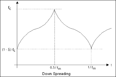
To get a flat CLK spectrum, a special curve called "Hershey Kiss â„¢" is used as the modulation waveform (Figure 2).

Figure 2. "Hershey Kiss" modulation waveform
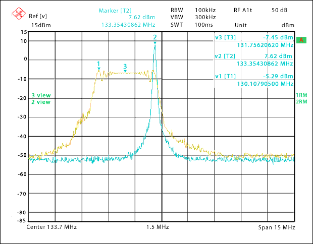
The clock expanded by the waveform shown in FIG. 1 or FIG. 2 has a flat power spectral density in the spread spectrum range. The curve shown in Figure 3 is the clock spectrum of the MAX9492 with and without spread spectrum. In the case of spread spectrum, the spread rate δ is -2.5%-downward spread spectrum; the modulation rate fm is 30kHz, and the nominal frequency fC of CLK is 133.33MHz. The spectrum curve is obtained by testing with Rohde & Schwarz spectrum analyzer, in which the resolution bandwidth is 100 kHz and the scanning frequency is 10 Hz. It can be seen from the test results that the peak of the spectrum is reduced by about 13dB, which is the same as the attenuation of the fC harmonic. This shows that the spread-spectrum CLK can provide 13dB of EMI suppression at the peak of the spectrum.

Figure 3. Estimation of spectrum EMI suppression in the case of MAX9492 spread spectrum and non-spread spectrum Designers often need to understand the relationship between EMI suppression and spread spectrum CLK parameters. In order to obtain this relationship, we need to first calculate the spectrum of spread spectrum CLK. According to the above definition, the signal spectrum is the frequency-dependent power density. To simplify the analysis, we only consider the fundamental harmonics of the CLK signal. For CLK without spread spectrum, it can be expressed as:

For spread spectrum CLK can be expressed as:

In the formula,
 Is the modulation waveform. The unspread spectrum of CLK is a spectral line at fC with an amplitude of:
Since the spectrum is just a spectral line, its amplitude is independent of the resolution bandwidth B of the spectrum analyzer. However, the spectral amplitude of the spread spectrum CLK depends on the resolution bandwidth B. Since the power of the spread spectrum CLK is fairly evenly distributed in the Δf band, the power obtained by using a spectrum analyzer with a resolution bandwidth of B is approximately:

In this way, we can get the EMI suppression rate S as:
EMI suppression rate (dB)
 (1)
(1) Combining the above spread spectrum CLK parameters: spread rate δ, CLK frequency fC and modulation type, we can calculate S using the following method:
Spread down or up:
 (2a)
(2a) Center spread spectrum:
 (2b)
(2b) It should be noted that when fSW << fm << fC, the EMI suppression rate S is independent of the modulation rate fm, where fSW is the scan rate of the spectrum analyzer.
For example, the delta and fC of MAX9492 are -2.5% and 133.3MHz, respectively, and substituted into formula (2a), the EMI suppression rate can be calculated:

According to the test results shown in Figure 3, the peak EMI is reduced by 12.91dB, and the average EMI suppression of the spread spectrum is 15.07dB. In general, when estimating the EMI suppression between peaks, the result calculated by Equation 2 may be 1dB to 2dB higher due to fluctuations in the spread spectrum. For peak and average EMI suppression, the calculated value is very close to the measured value.
Using a simple calculation formula for EMI suppression, designers can quickly calculate the expansion rate based on the desired EMI suppression rate, CLK frequency, and resolution bandwidth required by electromagnetic compatibility.
The XLPE insulated flame retardant shipboard control cables are intended for control system on shipboard and off-shore building.
Product marking: factory name, type, rated voltage.
Core marking: color marking or printed numbers.
Name:150/250V PVC insulated shipboard control cable
Model:DA/SA/NSA/NA type:CKVV, CKVV80, CKVV90, CKVV82, CKVV92
Name:150/250V XLPE insulated shipboard control cable
Model:
DA/SA/NSA/NA type:CKJV, CKJV80, CKJV90, CKJV82, CKJV92, CKJ82, CKJ92
SC/NC/NSC type:CKJPF, CKJPF80, CKJPF90, CKJPF86, CKJPF96, CKJ86, CKJ96
CKJPFP, CKJPFP80, CKJPFP90, CKJPFP86, CKJPFP96, CKJP86, CKJP96
CKJPJ, CKJPJ80, CKJPJ90, CKJPJ85, CKJPJ95, CKJ85, CKJ95
CKJPJP, CKJPJP80, CKJPJP90, CKJPJP85, CKJPJP95, CKJP85, CKJP95
Specification:(2~37)×(0.5~2.5)mm2
Executive Standards:IEC60092-350, IEC60092-376
Application:The cable is intended for control system or shipboard and offshore building
Flame Retardant Marine Control Cable
High Voltage Cable,Flame Retardant Marine Control Cable,Cable Cover High Voltage,Multi Core Control Cable
Jiangsu Jiangyang Special Cable Co,.Ltd. , https://www.jymarinecable.com