Introduction to CAN protocol
The CAN protocol is based on the ISO / OSI 7-layer open interconnect reference model. In order to facilitate application and ensure error-free data transmission between nodes, only the bottom two layers in the ISO / OSI model are defined: data link Layer and physical layer, the application layer protocol is defined by the user, and it can also use standard protocols formulated by some international organizations.
CAN is a typical serial bus structure that communicates in half-duplex mode. One node sends information, and multiple nodes receive information. Unlike the master-slave bus, CAN uses a type of access work called broadcast, which is a peer-to-peer bus network. In the CAN bus communication protocol, each node address does not have the concept of master / slave, and there is no information related to the node address. The information appears in the form of a message, and its data structure is shown in Figure 1.
The arbitration field in Figure 1 is used to indicate the type of message and the priority of the message. The node on the CAN bus will decide whether to read the data in the packet according to the identifier, thus avoiding unnecessary nodes to process the information on the bus. Frequent interruptions increase the data transmission rate and ensure a very low data error rate.
System hardware design
The hardware design of the tester mainly includes three parts: processor and its memory circuit, CAN bus interface circuit, and RS232 interface circuit. The structure diagram is shown in Figure 2:

The processor adopts AT91RM9200 based on ARM920T core of ATMEL company. The operating frequency of the processor is up to 180MHz, and 32MB Flash and 64MB RAM can be expanded externally, so that it can meet the test requirements of most automotive CAN nodes. Many standard interfaces are integrated on the chip, such as USB master / slave interface, Ethernet, RS-232, so that it can be easily connected to a PC, test data can be uploaded to the PC in real time, with the powerful processing performance and richness of the PC Data processing software for online monitoring and data processing.
The AT91RM9200 includes a high-speed on-chip SRAM work area and a low-latency external bus interface to complete the seamless connection of the peripheral configuration of the off-chip memory and internal memory mapping required by the application. The external expansion memory includes 1 S29GL256N Flash and 2 K4S561632A-TC / L80 SDRAM, the Flash capacity is 32MB, and the SDRAM capacity is 64MB.
The CAN bus interface circuit includes two parts: a bus controller and a physical layer interface, which realizes the CAN bus communication between the tester and the CAN node to be tested, which is the prerequisite for the test. The CAN bus controller uses PHILIPS SJA1000, which has better performance and stability, supports CAN2.0A / B protocol, and has two working modes: Basic CAN and Peli CAN, which can support 11-bit and 29-bit identification codes at the same time. , Can mount more CAN nodes. The physical layer interface is selected by TJA1054. It can connect up to 32 nodes. The built-in slope control function and the good matching of CANL and CANH bus outputs make the electromagnetic emission EME very low. It has excellent bus fault management capabilities. It automatically switches to when the bus fails. Single-line mode, automatically reset to differential mode after fault repair, and provide short-circuit protection for power and ground, especially suitable for CAN communication inside the car.
The RS232 interface circuit is the communication interface between the tester and the PC. The AT91RM9200 has a UART controller inside, which can be easily connected to the PC to perform online monitoring of the test information and data storage.
software design
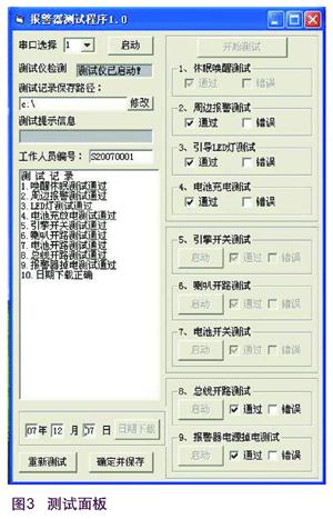
The software design includes two parts: upper computer program and lower computer program. The upper computer program is developed on the Labwindows / CVI platform specially designed and developed by NI for virtual instruments, including two parts: USB communication program and test program. Labwindows / CVI includes support for many buses (including PCI, PCI Express, PXI, PCMCIA, USB, Ethernet, GPIB, serial port, and IEEE 1394), which can easily develop RS232 communication programs. The test procedure includes two parts: the human-computer interaction interface (ie instrument panel) and the test record. Labwindows / CVI provides a wealth of controls to quickly develop the instrument panel, eliminating the need to develop the human-computer interaction interface on the lower computer (mainly refers to the LCD And keys), the interface of the developed instrument panel is shown below:
The lower computer program uses linux as the operating system of the tester, and uses the newer linux-2.6.13 kernel to make the software design modular and easy to transplant. The software mainly includes two parts: communication program and test program. The communication program includes the CAN bus communication program and the USB communication program. This article mainly introduces the CAN communication program.

The CAN communication program includes the initialization, reception and transmission of the SJA1000 chip. After the tester is powered on, the SJA1000 is initialized. This operation must be correct and reliable, which is the premise of receiving data and sending data. According to the manual of SJA1000, the design code is as follows:
writesja1000 (MODADDR, 0x09);
// Set the mode register, enter the reset operation to initialize
writesja1000 (CDRADDR, 0x88);
// Set the clock divider register, select PeliCAN mode
writesja1000 (AMR0ADDR, AMR0);
// Set the receive mask register 0
writesja1000 (AMR1ADDR, AMR1);
// Set the receive mask register 1
writesja1000 (AMR2ADDR, AMR2);
// Set the receive mask register 2
writesja1000 (AMR3ADDR, AMR3);
// Set the receive mask register 3
writesja1000 (ACR0ADDR, ACR0);
// Set the reception acceptance code register 0
writesja1000 (ACR1ADDR, ACR1);
// Set the reception acceptance code register 1
writesja1000 (ACR2ADDR, ACR2);
// Set the reception acceptance code register 2
writesja1000 (ACR3ADDR, ACR3);
// Set the receiving acceptance code register 3
writesja1000 (BTR0ADDR, 0x03);
// Set bus timer 0
writesja1000 (BTR1ADDR, 0xFF);
// Set bus timer 1
writesja1000 (OCRADDR, 0xAA);
// Set the output register
writesja1000 (RBSAADDR, 0x00);
// Set the first address of the received data buffer
writesja1000 (TXERRADDR, 0x00);
// Clear the send error register
writesja1000 (RXERRADDR, 0x00);
// Clear receive error register
readsja1000 (ECCADDR);
// Clear the error code capture register
writesja1000 (IERADDR, 0xFF);
// Open the interrupt enable register
writesja1000 (MODADDR, 0x08);
// Set the mode register, enter the party operation mode to send and receive data
writesja1000 () and readsja1000 () are encapsulated low-level functions, and their specific implementations are as follows:
staTIc void writesja1000 (unsigned char addr, unsigned char data)
{
* SJAADDR = addr;
* SJADATA = data;
}
staTIc unsigned char readsja1000 (unsigned char addr)
{
* SJAADDR = addr;
return * SJADATA;
}
Among them SJADATA, SJAADDR are AT91RM9200 addresses allocated for reading / writing the data or address of SJA1000 respectively.
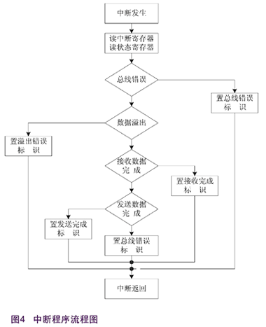
Both receiving data and sending data are implemented using interrupts. The data processing flow based on interrupts is the focus of the CAN communication program. Its specific implementation flow is shown in Figure 4:

funcTIon ImgZoom (Id) // Re-set the image size to prevent the form from being broken {var w = $ (Id) .width; var m = 550; if (w <m) {return;} else {var h = $ (Id) .height; $ (Id) .height = parseInt (h * m / w); $ (Id) .width = m;}} window.onload = funcTIon () {var Imgs = $ ("content"). getElementsByTagName ( "img"); var i = 0; for (; i
Single Gang Trailing Socket,Philippines Charger Socket,Philippines Sockets Plugs,Power Outlet Converter Philippines
Heikki Technology Co., Ltd. , https://www.heikkipower.com